About cookies on this site Our websites require some cookies to function properly (required). In addition, other cookies may be used with your consent to analyze site usage, improve the user experience and for advertising. For more information, please review your options. By visiting our website, you agree to our processing of information as described in IBM’sprivacy statement. To provide a smooth navigation, your cookie preferences will be shared across the IBM web domains listed here.
Tutorial
Setting up a high-availability VPN between IBM Cloud and OCI
Learn how to configure a high-availability VPN between IBM Cloud and OCI using a hub-and-spoke architecture for seamless connectivity
On this page
This tutorial explains how to set up a high-availability (HA) VPN connection between Oracle Cloud Infrastructure (OCI) and IBM Cloud using a hub-and-spoke architecture with an Active-Active cross-zone setup. In this approach, all Spoke VPCs on IBM Cloud route traffic through a central Hub VPC to access OCI resources, simplifying connectivity. On the OCI side, we use two Fault Domains within the same Availability Domain, as is the case in the Madrid region.
To help with deployment, we provide a sample Terraform script for easy setup. You can download the Terraform script from the gitHub repository: How to connect OCI and IBM Cloud through a VPN in a high-availability (HA) scenario.
Note: This example is for learning purposes only and is not recommended for production use.
Proposed architecture: Active-Active
To ensure high availability, two VPN gateways must be deployed for each cloud provider:
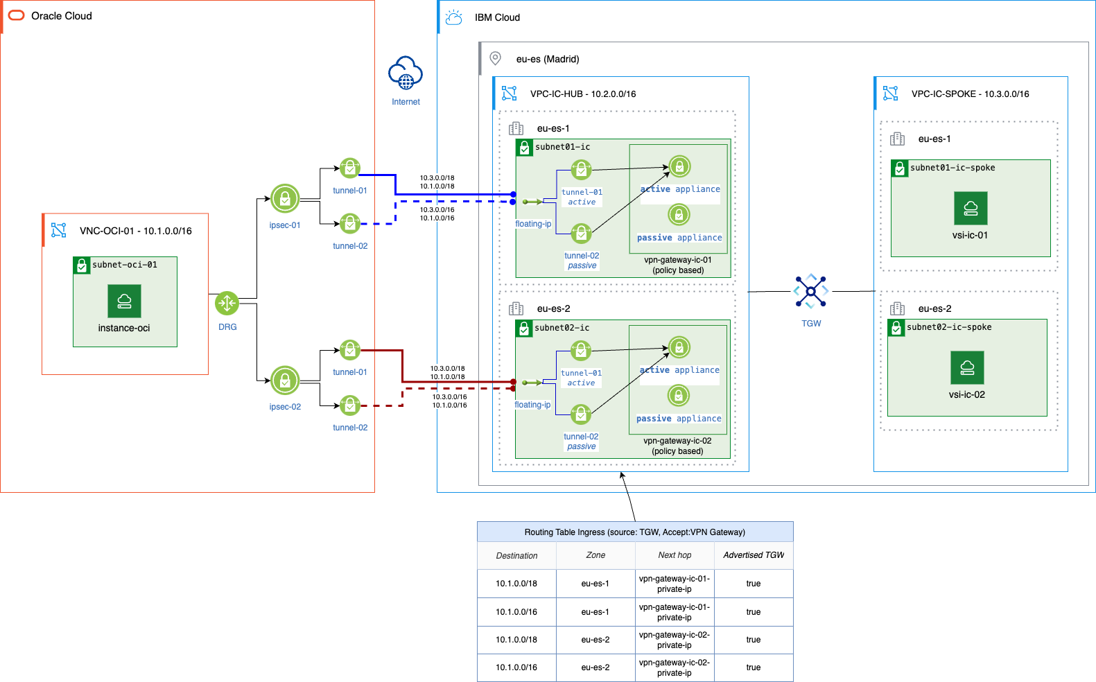
IBM Cloud: One VPN gateway per zone, each with two appliances in an Active-Passive setup. Each gateway supports multiple tunnels.
OCI: The Site-to-Site VPN is deployed in a single Availability Domain, with each tunnel placed in a different Fault Domain and managed by a separate appliance.
On IBM Cloud, we configure one policy-based VPN gateway per zone, each with two tunnels connecting to two OCI VPN IPsec tunnels in different fault domains. The Transit gateway (TgW) ensures traffic stays within the same zone between spokes and the hub, as long as the same CIDR range and prefix are advertised via the Ingress routing table.
Tunnels configuration
On IBM Cloud, a total of four tunnels will be used, two per VPN gateway in an Active-Passive setup. Prefix prioritization determines which tunnel is active.
VPN gateway Zone 1
Tunnel 1 (Active): 10.3.0.0/18 (local) ↔ 10.1.0.0/18 (remote)
Tunnel 2 (Passive): 10.3.0.0/16 (local) ↔ 10.1.0.0/16 (remote)
VPN gateway Zone 2
Tunnel 1 (Active): 10.3.0.0/18 (local) ↔ 10.1.0.0/18 (remote)
Tunnel 2 (Passive): 10.3.0.0/16 (local) ↔ 10.1.0.0/16 (remote)
Traffic flow
OCI to IBM Cloud (left to right flow)
Traffic starts from an OCI instance.
The routing table forwards traffic to the DgR with ECMP enabled, selecting a tunnel.
Due to identical
/18prefixes on two active tunnels, one is chosen randomly.Traffic enters an IBM Cloud zone and reaches the correct VSI via the TgW.
Policy-based routing prevents traffic forwarding across zones unless destined for a VPC behind the TgW.
IBM Cloud to OCI (right to left flow)
Traffic starts from a VSI in a Spoke VPC.
It passes through the TgW, staying in the same zone.
The traffic reaches the VPN gateway in that zone.
The active tunnel is used to encrypt and send packets.
Traffic terminates at the OCI Site-to-Site VPN, reaching the target instance.
Failover scenarios
IBM Cloud
If one appliance fails, the other takes over, maintaining the tunnels. The VPC route table ingress is updated with healthy remote CIDR tunnels and advertised to the Transit gateway (TgW).
If one zone goes down, its VPN gateway and tunnels also go down. The affected routes are removed from RT Ingress and no longer advertised to the TgW. However, the other zone continues to support connectivity between IBM Cloud (IC) and OCI.
OCI
If one appliance fails, the tunnel it manages goes down. The IBM Cloud VPN gateway detects the failure, updates the VPC route table, and notifies the TgW. This may cause asymmetric traffic, for example, if Tunnel 1 fails, traffic from Zone 1 may route through Zone 2, while return traffic follows a different path. This is supported on IBM Cloud, as its VPN gateway allows asymmetric traffic.
If one fault domain goes down, at least two tunnels of the OCI Site-to-Site VPN remain active. However, OCI does not let you choose specific fault domains for appliance placement.
Security Association (SA) considerations
The OCI Site-to-Site VPN creates two tunnels, each supporting multiple CIDR blocks (local and remote). OCI assigns one SA per CIDR, while IBM Cloud VPN gateway creates a single SA for all CIDRs.
Key considerations:
This difference is expected due to how each system handles encryption domains and traffic selectors.
Peer-only negotiation must be enabled on the IBM Cloud VPN gateway, allowing OCI to control IKE negotiation for each SA/CIDR. Bidirectional negotiation causes conflicts, keeping only one SA active.
Perfect Forward Secrecy (PFS) is not supported in this setup and must be disabled in IPsec policies on both sides.
Terraform deployment: Active-Active setup
Below is a sample Terraform code for deploying the Active-Active architecture. This is intended for learning and testing purposes and should not be used in production without modifications.
The following resources will be deployed:
IBM Cloud
One Transit VPC (10.2.0.0/16)
One Spoke VPC (10.3.0.0/16)
One Transit gateway (TgW)
One Ingress Routing Table
Two VPN gateways(1 per zone)
- Two tunnels per VPN gateway
One VSI in each zone within the Transit VPC
OCI
One Virtual Cloud Network (VCN) (10.1.0.0/16)
Two Site-to-Site VPNs
- One tunnel per appliance
One Oracle Linux instance
One Dynamic Routing gateway (DRg)
Steps to deploy using Terraform
Download the code by running the following commands:
git clone https://github.com/IBM/vpn-ha-ic-oci-hub-spokecd vpn-ha-ic-oci-hub-spoke/terraformSet IBM Cloud CLI environment variables by running the following commands:
export IC_REgION=$IBM_REgIONexport IC_API_KEY=$IBM_API_KEYAuthenticate with OCI:
oci session authenticateget the OCI Compartment OCID:
export compartment_ocid=$(cat ~/.oci/config | grep tenancy | head -1 | cut -d '=' -f 2 | sed 's/^ *//g')Ensure the SSH key exists. Otherwise, create one.
export ssh_key_name="SSH_KEY_NAME"Initialize and deploy with Terraform by running the following commands:
terraform initterraform plan -var "compartment_ocid=ssh_key_name" -out plan.outterraform apply plan.outget OCI instance private IP:
ssh opc@$(terraform output instance-oci | sed "s/\"//g") ip addr showVerify connectivity:
Log into IBM Cloud VSI (Zone 1) and ping OCI instance:
ssh root@$(terraform output vsi-ic-01 | sed "s/\"//g") ping 10.1.1.109Log into IBM Cloud VSI (Zone 2) and Ping OCI instance:
ssh root@$(terraform output vsi-ic-02 | sed "s/\"//g") ping 10.1.1.109
Alternative architecture: Active-Passive (discarded scenario)
This architecture is similar to the Active-Active solution but uses only one tunnel per gateway.
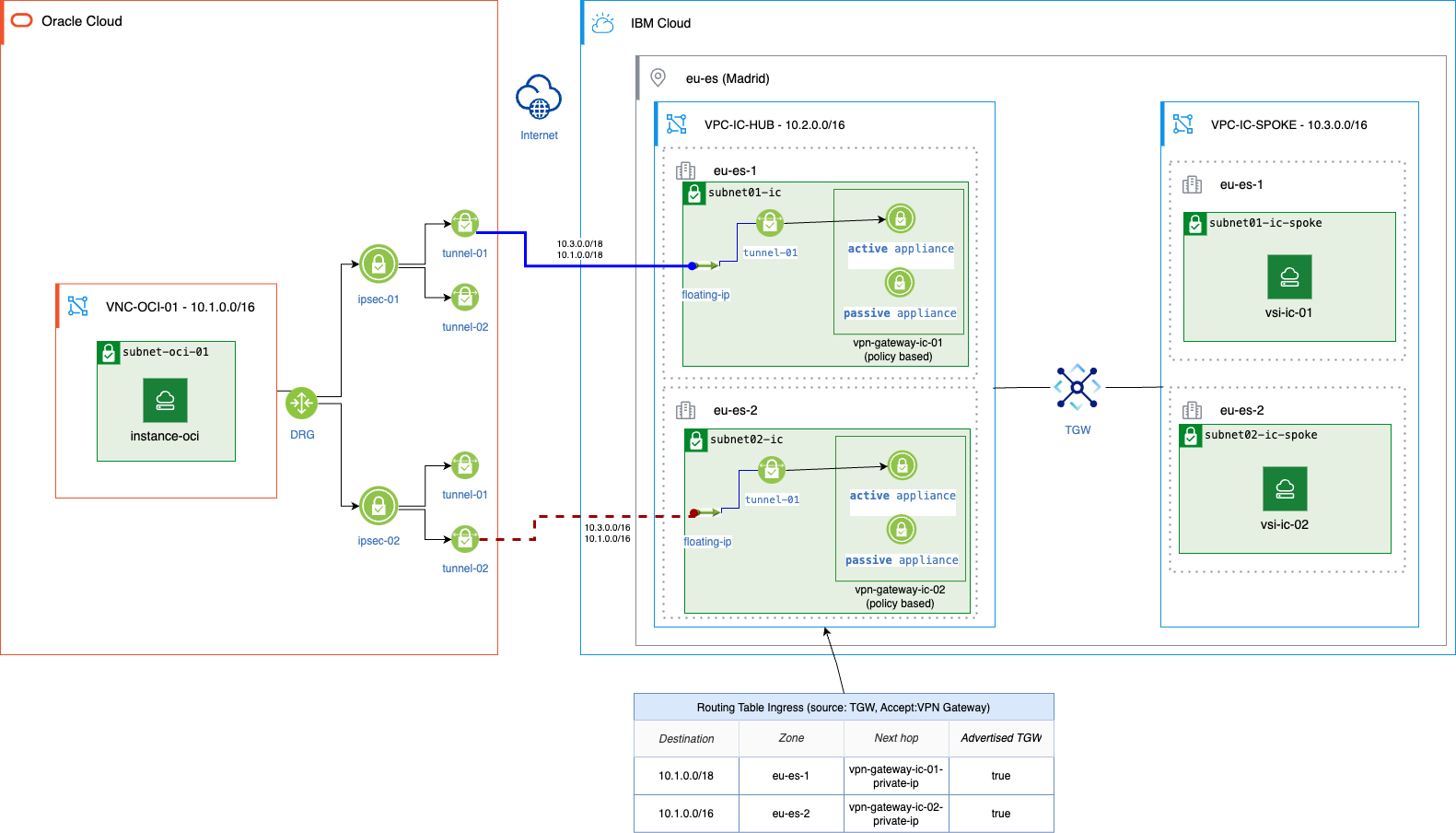
Tunnel Configuration:
VPN gateway (Zone 1)
- Tunnel 1: 10.3.0.0/18 (local) ↔ 10.1.0.0/18 (remote) (Active)
VPN gateway (Zone 2)
- Tunnel 1: 10.3.0.0/16 (local) ↔ 10.1.0.0/16 (remote) (Passive)
Traffic flow and failover:
The preferred path is through Zone 1 via VPN gateway 1, as it has a more specific prefix.
If the IPSec1 appliance on OCI goes down, the corresponding tunnel also fails.
The route in RT Ingress is removed, and TgW redirects traffic to VPN gateway 2 in Zone 2.
Challenges on the OCI side:
OCI does not allow control over which Fault Domain the Site-to-Site VPN appliances are placed in.
Customers cannot determine the exact location of the appliances or ensure that active/passive tunnels are in separate Fault Domains.
OCI schedules maintenance with a rule that two appliances from the same Site-to-Site VPN are not maintained simultaneously.
However, in this scenario, maintenance on different Site-to-Site VPNs may overlap, causing potential downtime.
Due to these limitations, the Active-Passive setup was discarded in favor of the Active-Active architecture.
Summary
This tutorial guided you through setting up a high-availability (HA) VPN connection between Oracle Cloud Infrastructure (OCI) and IBM Cloud using a hub-and-spoke architecture. Traffic from all Spoke VPCs on IBM Cloud is routed through a central Hub VPC, simplifying connectivity to OCI and avoiding individual Spokes managing their own connections.
To make deployment easier, we provide a sample Terraform script. While this script is useful for learning and testing, it is not recommended for production use.
FAQs
Does the VPN gateway on IBM Cloud allow asymmetric traffic?
Yes
Does a policy-based VPN gateway allow asymmetric traffic across two tunnels (with the same prefix and ranges)?
No
Does the Transit gateway (TgW) maintain traffic within the same zone if identical prefixes are advertised in both zones?
Yes
Can we choose which fault domains the Site-to-Site VPN in OCI is deployed in?
No
Which CLI versions were used in this PoC?
Terraform v1.9.7 and OCI client 3.49.2